10.7 ENGINE INSTRUMENTATION
To evaluate the quality of his design during and after test, to monitor progress, and finally to "sell" his engine to the customer, the designer needs recorded evidence of the engine's overall performance. These records may broadly be classified by two categories: visual inspection and measurements.
Visual inspections are self-explanatory. They consist, often after disassembly of a component, of an inspection for cracks, fractures, deformations, signs of overheating, etc. Surface discolorations may often be a sign of fluid leaks. In fact, minute amounts of a dye have been added to a number of propellants such as alcohol- and the kerosene-type fluids, which leave qualitative evidence at the leak spot. Visuarchecks assume a particularly important role in the event of serious malfunctions. As a rule, they do not require special preparations by the designer, except perhaps written instructions (drawing callouts) and forms.
By contrast, the second category, measurements, does require consideration during engine design. To make the required measurements, instruments are needed. Some of these may be simple devices such as gages, micrometers, and torque wrenches, which can only be used before and/or after test, and which will not be discussed here. However, for the majority of the instruments used for engine design and performance evaluation, particularly during test, the designer must provide adequate provisions for installation. Furthermore, the correct execution of command signals fed to the engine and the behavior of the major performance parameters must be transmitted back to the vehicle and from there to ground, either by hard wire (static tests) or by means of a radiating telemetry system (flight). The instrumentation of a liquid rocket propulsion system is a large field, and within the framework of this book we can merely point out its significance. The engine designer must be fully cognizant of it, and must be sure to consult the development engineer and the instrumentation specialist at the very beginning of his design.
Principal Types of Instrumentation
Instrumentation signals to the vehicle are generated by engine-mounted end organs or transducers, with typical applications as follows:
Temperature gages.-Thermocouples or resistance bulbs are the principally used types. Their main application is for fluid-temperature measurement at the pump inlets for the determination of mass flow rates in combination with volume-reading flowmeters. Also, temperature measurements are made in other critical metal or fluid areas, such as at the gas generator, at the turbine inlet, at the gas storage vessels, and at solid propellant gas spinners, if such are employed.
Pressure switches.-A typical application would be a signal from the engine to the vehicle when thrust (chamber pressure) reaches a preset value during decay to initiate start of the next stage and separation of the spent one.
Pressure transducers.-A variety of types is available: strain gages, capacitance types, variable reluctance types, potentiometer types. piezoelectric types. Table 10-2 lists, among others, important pressures which can be expected to require monitoring and transmission to the vehicle and its telemetry system.
Accelerometers.-It is often important to measure the vibrations occuring in various locations of the engine system, and how these vary between static (tiedown) firing and flight. Accelerometers are used for this purpose and also, instead of pressure switches, to sense and signal thrust decay for staging.
Tachometers and flowmeters.-Small magnets mounted in a suitable manner to rotating parts of flowmeters or turbine wheels will induce periodic voltage pips in stationary coils. By counting the pips as a function of time, turbopump speed or volume flow rate can be determined.
Depending on the type of transducer used, a certain amount of signal conditioning will have to be provided at or near the transducer. Some of the latter give relatively weak signals (thermoelements, capacitance-type gages, tachometers, and flowmeters), which must be amplified prior to transmission. In other cases, it may be desirable to convert a digital signal into an analog one, prior to transmission (tachometers, flowmeters). Small though the electronic (solid state) signal condition packages may be, room in a compatible environment must be provided for them on the engine. Under adverse conditions, it may be necessary to mount the conditioners on the vehicle near the engine.
Some transducers generate their own electric signal, such as the thermoelements, piezoelectric elements, and many of the flowmeters and tachometers. Most others, however, require an external electrical input which they modify as a function of the quantity sensed. Potentiometers, capacitors, inductances, and resistance temperature bulbs are examples. Resistance types can use ac or dc; capacitance and inductance types require ac. Typical instrumentation power supplies are 28 volts and 5 volts dc, and 115 volts ac, 400 cps . Certain transducers with built-in electronics receive 28 volts dc, chop, use and rectify it, and then return 5 volts (maximum) signals (dc-to-dc transducers). Strain gages and variable reluctance gages are typical examples.
Table 10-2 presents the basic static-firing measurement list for an engine of an A-1 stage. In practice, particularly during early development, this list may be expected to be augmented by special measurements, requiring additional instrumentation such as flowmeters, temperature gages, high-accuracy pressure gages, vibration pickups, and strain gages.
Instrumentation Installation
Some basic design considerations for correct installation of instrumentation end organs (pickups, sensors) will be briefly discussed.
1. Temperature Sensors
The most widely used temperature sensors are thermocouples. In rocket engine application, thermocouples are subject to certain measurement errors. Among these are:
Velocity errors.-Fluid friction may cause an excessive temperature reading, particularly at high fluid velocities. Suitable protection which does not affect the true measurement may have to be provided.
Conductive errors.-A heat leak may exist from probe to support. Figure shows a
Table 10-2.-Basic Liquid Propellant Rocket Engine Measurement List (A-1 Stage Engine)
| Parameter | Range |
|---|---|
| Thrust | |
| Thrust chamber pressure (injector end) | 0-1200 psig |
| Fuel pump inlet pressure | |
| Oxidizer pump inlet pressure | |
| Fuel pump outlet pressure | |
| Oxidizer pump outlet pressure | |
| Fuel injection pressure | 0-1500 psig |
| Oxidizer injection pressure | 0-1500 psig |
| Heat exchanger outlet pressure | 0-1000 psig |
| Gas generator chamber pressure | |
| Turbine inlet pressure | |
| Turbine discharge pressure | 0-30 psig |
| Stored gas container pressure | |
| Fuel pump inlet temperature | Ambient- |
| Oxidizer pump inlet temperature | Ambient to |
| Cooling jacket inlet temperature | Ambient- |
| Cooling jacket outlet temperature | Ambient- |
| Turbine inlet temperature | Ambient |
| Stored gas container temperature | |
| Fuel flow | |
| Oxidizer flow | |
| Turbopump speed | |
| Electric bus -ltage | 20-35 volts dc |
| Spark igniter OK | On/off |
| Miscellaneous valve positions | On/off |
thermocouple well proposed by B. N. Bose (ISA Journal, Sept. 1962) designed to offset this effect.
Carbon deposits.-In systems using kerosenebased fuels, carbon deposits may cause erratic thermoelectric and grounding effects. While certain electrical connections are possible to minimize this, regular cleaning and sometimes replacement of the probe is required. The engine designer must consider this need for easy accessibility of the instruments.
Installation of resistance thermometers or "bulbs" is governed by similar consideration.
2. Pressure Gages
Two principal types of pressure measurements are usually conducted during rocket engine testing: static and dynamic. As a rule static measurements are employed to record, with high accuracy, steady-state conditions or parameters varying only very slowly. Dynamic measurements are used where rapidly changing conditions
 Figure 10-21.-Properly designed thermocouple well (installed in a 4 -inch pipe).
(transients) must be recorded, with rapid response but at some sacrifice in accuracy.
Because of the higher accuracy usually desired for static measurements, the sensitive transducers are often mounted in environmentcontrolled boxes to protect them against vibration, temperature (both ambient and of the measured medium), and other influences. They are therefore usually mounted some distance away from the engine on the test-stand structure or on the vehicle, at the end of several feet of tubing. which reduces frequency response below signifi- cant levels. A transducer thus mounted, in combination with a good inking recorder or precision gage, may have a full span response time of about 1 second. It would be pointless to connect such a transducer to an oscillograph.
For certain parameters it may be desirable to combine accuracy with at least some frequency response. By shortening the line length to, for instance, 18 inches, a given setup may have a flat frequency response up to 25 cps . In these cases it will be the burden of the engine designer to provide for means to mount and connect the transducer. It should be noted that it is tube length which affects response, while bends appear to have a negligible effect. Occasionally attempts have been made to improve response by filling the connecting line with a liquid. Apart from operational inconveniences, severe undamped oscillations may result and the practice is not recommended. Figure 10-22 shows a pressure transducer installed and connected to engine pressure taps.
For frequency responses in the range from 100 to 2000 cps , close-coupled mounting of the transducer is required. Typical transducers, resembling a spark plug, are directly screwed into the instrumentation boss (fig. 10-23). It is important that the resonant frequency of the combined tap-and-transducer cavity should be well above that
 Figure 10-22.-Pressure transducers installed and connected to engine pressure taps (lower right).
 Figure 10-23. - Typical installation of a thrust chamber pressure transducer.
 Figure 10-24.-Acoustic equivalents of pressure transducer mounting cavities.
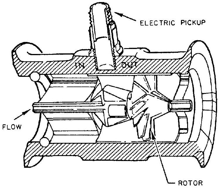 Figure 10-25.-Turbine-type flowmeter.
ducting (fig. 10-25). Turbine flowmeters are very sensitive to changes in upstream duct configuration. Once calibrated as installed, however, they exhibit a high degree of precision.
Accelerometers and Strain Gages
These are almost always applied externally, in connection with special measurement programs. At the time of engine systems design, no special consideration is usually required.